How do we manage risks in LNG facilities, from cryogenic leaks to flares and compressor skids?
The risk in LNG is real: cold leaks, hot flares, and fast skids can break systems and stop production.
We manage LNG risks by combining thermal or dual‑spectrum cameras, balanced coverage rules, sensible alarm thresholds, rugged materials, and clean integration into ESD and VMS/SCADA to catch problems early and cut false alarms.
I learned to respect LNG after a near-miss on a loading arm. The arm iced up fast. A thermal feed showed the cold spot first. That early alert kept the team safe.
Thermal vs dual-spectrum use cases?
Problems grow when the wrong sensor watches the wrong risk. That wastes budget and trust.
Thermal sees heat patterns and cold spots, ideal for flares, hot motors, and cryogenic leaks. Dual‑spectrum adds visible video for context, verification, and analytics, which reduces false alarms and helps operators act fast.
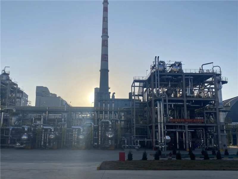
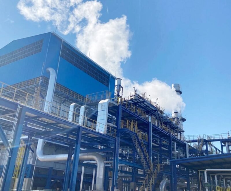
When I plan LNG safety, I start with the physics. Heat and cold drive the choice. Thermal maps temperature. Dual‑spectrum adds shape and color. That mix answers most use cases. In flare stacks, thermal tracks flame presence and intensity. In compressor skids, thermal watches bearings, housings, and motors against baseline. In cryogenic piping, thermal sees icing and cold leaks as clear anomalies. Visible video lets me confirm activity, check steam, dust, or sun glare, and review events. For perimeter and hot work areas, dual‑spectrum helps classify people, vehicles, and light sources. For gas detection, I pair thermal with dedicated detectors; thermal does not see methane directly unless the plume is hot or cold relative to background. I set rules: thermal for temperature-driven risks, dual‑spectrum for context and classification. I use analytics like flame detection, cold-spot alarms, and object filters to cut noise. This layered approach keeps coverage tight and costs reasonable.
Typical use mapping
| Area | Thermal role | Dual‑spectrum role | Notes |
|---|---|---|---|
| Flare stack | Flame presence, thermal intensity | Visual validation | Handles sun and night shifts |
| Compressor skid | Overheat detection | Visual maintenance checks | Baseline temp trending |
| Cryogenic lines | Cold-spot leak alerts | Ice/condensation visuals | Fast anomaly detection |
| Loading arm | Cold leakage, thermal drift | Operator guidance | Improve turnaround safety |
| Perimeter | Limited | People/vehicle classification | Reduce false alarms |
Coverage rules for piping, storage, and loading?
Too many cameras blind operators. Too few cameras miss events. Bad placement makes both worse.
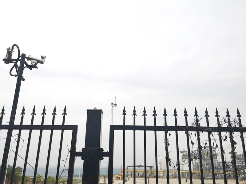
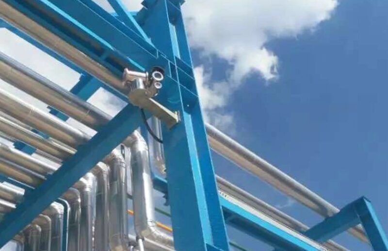
Use layered coverage: thermal on risk points and dual‑spectrum for context. Place sensors to see joints, valves, bearings, and transfer points. Maintain clear fields of view, avoid sun bounce, and set overlap for critical paths.
I start coverage by walking the route with operations. I mark hot and cold risk nodes: valves, flanges, expansion joints, pump seals, bearings, and loading arms. Thermal cameras face these nodes with angles that avoid sky glare and reflective steel. I set standoff distances that match the lens FOV to the target size. I add overlap across transfer lanes and around storage tank bases, where leaks pool. I keep clear lines by trimming vegetation and shielding from direct sun. I avoid placing cameras above hot process lines that can wash the view. For loading areas, I cover the arm hinge, flexible hose, and the drip trays with thermal, and place dual‑spectrum at operator walkways and control panels. I add one high-mount overview for incident review. Each camera gets a naming plan tied to P&IDs. I tag views to ESD zones so alarms lock out only the right systems. This design lowers alarm fatigue and speeds response.
Coverage checklist
| Zone | Points to cover | Sensor type | Placement tip |
|---|---|---|---|
| Piping | Joints, valves, supports | Thermal | Avoid reflective faces |
| Tank base | Annular ring, sump | Thermal + dual | Overlap for pooling |
| Loading | Arm hinge, hoses | Thermal | Mid-range standoff |
| Compressor | Bearings, housings | Thermal | Stable mount, minimal vibration |
| Walkways | Operators, vehicles | Dual | Clear identification angles |
Alarm thresholds, analytics, and false‑positive control?
Alarms that cry wolf break trust. Alarms that wait too long miss the moment.
Set temperature thresholds from baselines, not guesses. Use time filters and region masks. Add dual‑spectrum confirmation. Use analytics like flare presence, cold‑spot tracking, and object filters to keep the signal clean.
I build thresholds on real data. I record one to two weeks of thermal baselines under common loads. I set alerts at delta changes, not absolute numbers: for hot gear, +15°C above baseline; for cryogenic lines, −20°C below ambient in defined regions. I apply dwell times, like five seconds, to avoid birds or reflections. I mask hot backgrounds. I use flare analytics to flag flame loss or excess temperature rise. I add dual‑spectrum checks to confirm motion types and light sources. I audit false alarms weekly and adjust masks and filters. I form a clear action tree: low alarm prompts inspection, high alarm triggers ESD interlocks. I keep the event log simple for operators. I include weather inputs when possible. I track false‑positive rate and aim for below two percent. This work takes time, but it makes the system trusted.
Controls that cut false alarms
- Delta thresholds from baseline
- Dwell time filters
- Region-of-interest masks
- Dual‑spectrum confirmation
- Weather-aware rules
- Weekly alarm audits
Materials and environmental resistance?
LNG areas punish weak hardware. Cold, salt, sun, and vibration destroy poor housings fast.
Use explosion‑proof, ATEX/IECEx‑certified housings, 316L stainless steel, IP66/67 sealing, anti‑corrosion coatings, wide temperature ratings, shock mounts, and sunshields. Choose lenses and windows that resist icing and abrasion.
I specify housings that match zone and gas group with valid ATEX/IECEx. I choose 316L stainless steel with marine grade coatings for coastal sites. I use IP66/67 seals and cable glands that hold against spray and dust. I pick germanium windows for thermal and tempered glass for visible, both with hydrophobic and anti‑ice coatings. I add heaters and blowers where icing is common. I use sunshields and insulated mounts in hot climates. I choose PoE or fiber with armored conduits to resist mechanical damage. I add shock mounts near skids to reduce vibration blur. I check UV resistance on plastics. I test for −40°C to +70°C operation, as sites swing wide. I standardize spares to cut downtime. These choices save maintenance hours and cut failures in storms or shutdowns.
Material spec snapshot
| Component | Preferred spec | Reason |
|---|---|---|
| Housing | 316L + ATEX/IECEx | Corrosion + compliance |
| Seals | IP66/67 | Dust and spray |
| Window | Germanium/tempered | Thermal/visible durability |
| Coatings | Marine grade | Salt resistance |
| Mount | Shock + sunshield | Vibration and heat |
Integration into ESD and VMS/SCADA?
Great alerts fail if they do not link to control. Slow links waste minutes.
Tie cameras to VMS for video and analytics, and to ESD/SCADA for alarms and interlocks. Use open protocols, clear tag mapping, and tested fail‑safe behavior. Document everything.
I integrate with what the plant trusts. I feed video and analytics into VMS with ONVIF, RTSP, or SDKs. I send alarm outputs to SCADA via dry contacts, Modbus, or OPC UA as the site prefers. I map tags to P&IDs and ESD zones. I set priorities and escalation. I test interlocks with operations. I simulate false alarms and real events. I define fail‑safe states if power or network drops. I document configurations so maintenance can adjust later. I train the team on simple steps. I keep logs clean and searchable. I plan redundancy for critical spots. This approach ties the sensing layer to action and keeps people safe.
Integration steps
- Choose protocols: ONVIF, RTSP, Modbus, OPC UA
- Map alarms to ESD zones
- Test interlock logic
- Define fail‑safe states
- Train operators
- Document and audit
FAQs: Can thermal see gas leaks? What detection ranges? How to avoid false alarms?
Many teams ask the same questions. Clear answers prevent costly mistakes.
Thermal does not see methane directly. It sees temperature contrasts like cold plumes from LNG leaks or hot combustion. Detection range depends on lens, target size, and contrast. False alarms drop with baselines, masks, and dual‑spectrum checks.

I explain that thermal cameras sense infrared radiation, not gas concentration. Methane is visually transparent to most thermal systems. If LNG leaks, the plume is very cold, so thermal can flag it as a cold spot against warmer surroundings. Hot flames and overheats are clear too. Range depends on sensor resolution, lens FOV, and the size and contrast of the target. Small leaks need close views and tight optics. Large flares show at long range. To avoid false alarms, I use baseline temperature maps, region masks, dwell times, and dual‑spectrum confirmation. I pair cameras with certified gas detectors for concentration measurement. This mix gives early awareness and solid numbers. I share examples from docks and skids where cold plumes were caught early, and repairs took hours, not days.
Quick answers
- Thermal sees contrast, not methane
- Cold plumes from LNG are detectable
- Range depends on FOV and resolution
- Use dual‑spectrum and gas detectors
- Tune thresholds and masks
Conclusion
Layer thermal and dual‑spectrum sensing, set smart rules, build rugged systems, and integrate cleanly to keep LNG sites safe and efficient.